What the turbocharger system does
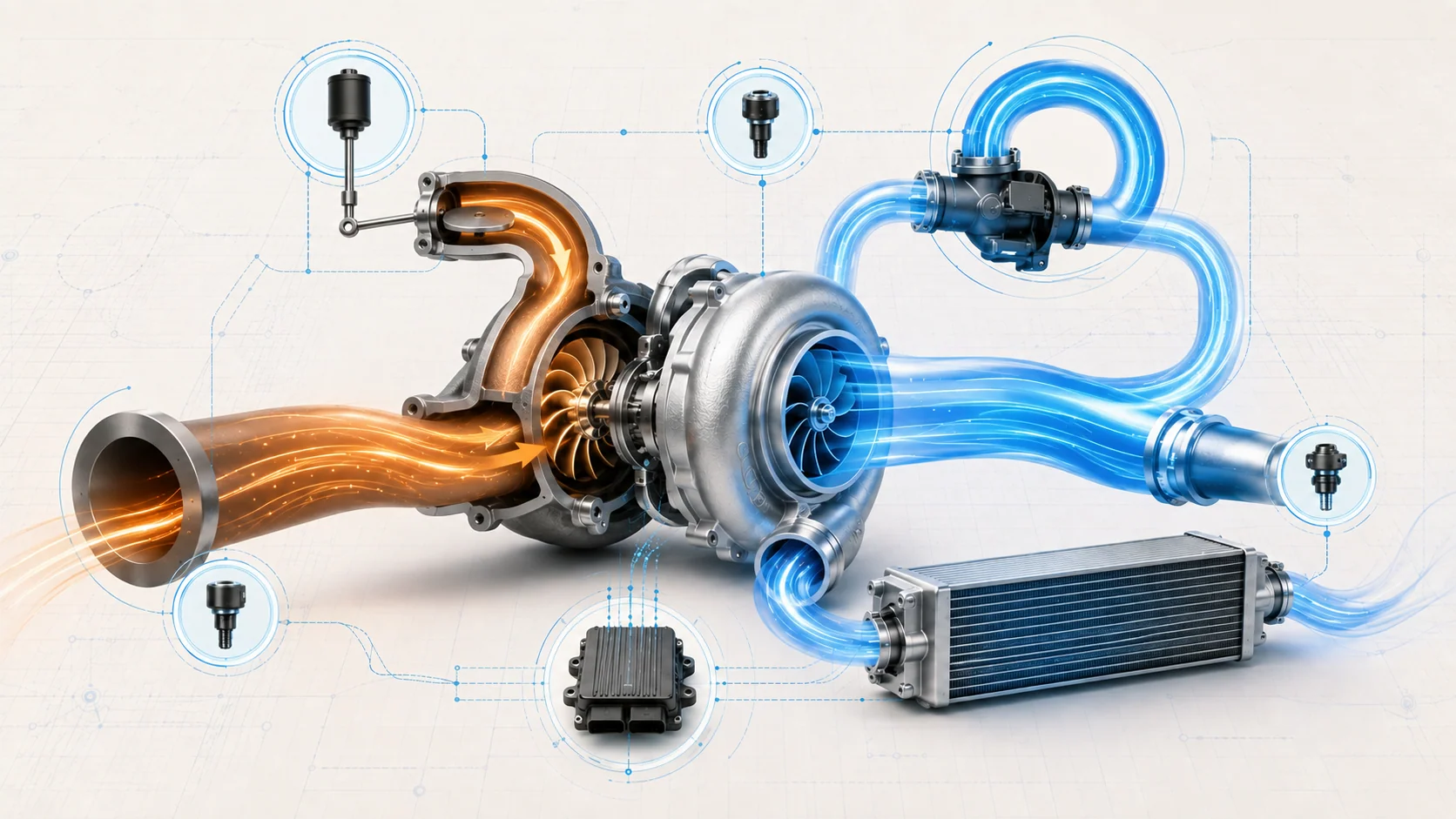
The turbocharger uses exhaust-gas energy to move more air through the engine than atmospheric pressure alone could provide. Exhaust flow spins a turbine. A common shaft drives a compressor, which draws in filtered air and sends pressurized air through the charge-air cooler to the throttle body and intake manifold.
Boost production is only one part of the system. The powertrain control module (PCM) must regulate turbine energy, manage compressor pressure during throttle changes, and decide whether several airflow and pressure signals agree. On the 2017-2025 Honda CR-V 1.5 Turbo Gas, diagnosis therefore involves the complete air path, electronic wastegate control, the compressor-bypass system, pressure and airflow feedback, and the exhaust path that drives the turbine.
This overview covers CR-V 4WD applications at both ends of the 2017-2025 range with the 1.5-liter turbocharged gasoline engine. The detailed operating and diagnostic examples were verified against 2025 L15BE service information. Exact thresholds, component locations, test commands, connector details, and repair procedures must come from current service information for the exact vehicle being repaired.
A turbo-related DTC identifies a monitored behavior that did not meet expectation. It does not, by itself, prove that the turbocharger assembly has failed.
The main functional sections
- Air inlet and airflow measurement: The air cleaner, inlet ducting, MAF sensing, and connections establish the air entering the compressor. Restrictions, leaks, contamination, and implausible signals can distort the PCM's airflow calculation.
- Turbine and compressor: Exhaust energy spins the turbine and common shaft; the compressor raises intake-air pressure. Bearing, wheel, shaft, housing, or flow problems can reduce output, but mechanical failure is only one category of boost fault.
- Charge-air cooler and pressure ducting: Pipes, hoses, joints, and the charge-air cooler carry compressed air toward the throttle body. A leak can release air the compressor already produced.
- Electric wastegate actuator and position feedback: The PCM changes wastegate position to regulate how much exhaust energy reaches the turbine. Position feedback lets the PCM compare requested movement with actuator response.
- Turbocharger bypass valve and control solenoid: The bypass path manages compressor-side pressure during rapid throttle changes. A valve, solenoid, diaphragm, hose, or control-path fault can affect response without being a wastegate failure.
- Pressure and airflow feedback: Boost-pressure, manifold-pressure, barometric-pressure, airflow, throttle, and engine-speed information give the PCM separate views of what the system is doing. These inputs are related but not interchangeable.
- Related PCV, EVAP, intake, and exhaust paths: Unmetered air, purge flow, crankcase ventilation, an exhaust leak, or a restriction can alter the same evidence used to judge turbo performance.
How normal boost control fits together
1. Exhaust flow creates compressor output
Exhaust gas turns the turbine, and the shaft transfers that energy to the compressor. Compression heats the incoming air, so the charge-air cooler reduces its temperature before the air reaches the engine. The entire inlet and charge path must remain sealed and unrestricted for measured airflow and delivered pressure to agree.
2. The wastegate regulates turbine energy
Closing the wastegate directs more exhaust through the turbine and tends to increase compressor speed and boost. Opening it allows some exhaust to bypass the turbine and reduces the energy available to the compressor. The electric actuator permits the PCM to vary wastegate position rather than treating boost control as a simple on/off function.
The actuator includes position feedback. This creates two separate diagnostic questions: whether the control circuit can drive the actuator, and whether the reported position is credible and follows the command. A circuit fault, a signal fault, or a sticking mechanical linkage can produce different evidence even though all involve the wastegate assembly.
3. The bypass system manages throttle transitions
When the throttle closes while the compressor is moving a large volume of air, pressure can build on the compressor outlet side. The bypass valve provides a managed route back toward the inlet side. The PCM controls the related solenoid so the diaphragm-operated valve can open or close for the operating condition.
The bypass valve does a different job from the wastegate. The wastegate regulates exhaust energy at the turbine; the bypass valve manages pressure on the compressor side. A click or command at the solenoid does not prove that the diaphragm, valve, hoses, and air path are sealed and working.
4. Sensor agreement closes the loop
The PCM can compare target boost with actual boost-system pressure, commanded wastegate movement with position feedback, and measured airflow with airflow inferred from pressure and engine operation. It can also compare barometric pressure with boost-sensor pressure when operating conditions should make those readings agree.
These comparisons answer different questions:
- Target versus actual boost asks whether the complete system delivered the requested pressure.
- Wastegate command versus position feedback asks whether the actuator and its reporting path followed the request.
- MAF versus calculated airflow asks whether independent views of engine airflow agree.
- Boost-sensor versus BARO correlation asks whether two pressure references are credible under the monitored condition.
- Intake-leak logic asks whether air is entering, leaving, or being estimated through an unexpected path.
The diagnostic task is to identify which mismatch is primary and which is a consequence.
What the related DTCs are telling you
| DTC | Diagnostic category | What it directs you to prove |
|---|---|---|
| P0045 | Electric wastegate actuator circuit or motor-current fault | Whether the actuator, its motor circuits and connectors, or the PCM control path can carry out the commanded movement |
| P006A | MAF/MAP airflow correlation | Whether the pressure and airflow inputs are credible and whether intake, PCV, purge, or air-path faults are distorting the airflow model |
| P00CF | Boost-sensor/BARO pressure correlation | Whether the two pressure signals agree under the monitored condition and whether a related sensor or circuit fault should be diagnosed first |
| P0299 | Turbocharger underboost | Whether pressure feedback is credible and whether inlet supply, charge-air sealing, bypass control, wastegate response, purge plumbing, exhaust flow, and turbo condition allow actual boost to reach target |
| P2279 | Intake-air leak or unmetered-air pattern | Whether the intake, PCV, EVAP purge, throttle, and turbo-to-throttle paths contain a leak or abnormal flow influence |
| P2563 | Wastegate actuator position feedback range/performance | Whether the actuator signal, related circuits, linkage, turbocharger-side mechanism, or control path explains implausible feedback |
| P2565 | Wastegate actuator position-sensor signal high | Whether a high feedback signal comes from the actuator/sensor side, wiring, connector, ground path, or PCM after external checks pass |
The code combination determines the order. A direct actuator-circuit, pressure-sensor, or position-signal fault can invalidate conclusions from an underboost monitor. An airflow-correlation or intake-leak fault can explain P0299 without a damaged turbocharger.
What the driver or technician may notice
Possible observations include:
- a malfunction indicator lamp with little immediate change in drivability;
- weak, delayed, or inconsistent acceleration under load;
- reduced-power operation or boost limited by the control strategy;
- an air-rush, hiss, whistle, or flutter associated with a leaking or incorrectly controlled air path;
- unstable idle or low-speed operation when unmetered air, PCV, or purge flow is involved;
- an intermittent fault that appears only near the conditions recorded in the stored snapshot;
- multiple airflow, pressure, purge, or actuator DTCs that must be diagnosed in priority order.
No single symptom proves a damaged turbocharger. Noise can come from an air leak, exhaust leak, bypass-control concern, or unrelated rotating component. Low power can originate outside the boost system.
Common failure categories
Air cannot reach the compressor correctly
A restricted air cleaner or inlet, damaged duct, loose connection, or implausible MAF signal changes both the air available to the compressor and the information used to calculate load. This can create an airflow-correlation fault, contribute to underboost, or make later boost conclusions unreliable.
Compressed air escapes before reaching the engine
A leak at a hose, pipe, joint, charge-air cooler, throttle connection, or related path lets compressor output escape. The turbo may work harder while manifold pressure still falls short of target. Charge-air integrity should be proved before condemning the turbocharger for P0299.
Wastegate control does not follow the command
The actuator motor, wiring, connector, position-feedback circuits, linkage, wastegate mechanism, or PCM control path can prevent correct movement or make the reported position unreliable. P0045 is primarily an actuator-control circuit/current category. P2563 is a position range/performance category. P2565 is a high position-signal category. They overlap around the actuator but do not prove the same failure.
The bypass system does not manage compressor pressure correctly
A bypass valve, diaphragm, solenoid, hose, or control-path concern can change boost response, especially during throttle transitions. Valve and solenoid tests must be interpreted with the connecting plumbing and the sealed air path considered together.
Sensor correlation or the airflow model is wrong
MAF, MAP, BARO, boost-pressure, throttle, PCV, EVAP purge, and intake sealing all affect the PCM's view of airflow and pressure. Resolve direct sensor, reference, or circuit faults before using performance codes to judge mechanical turbo output.
Exhaust energy cannot drive the turbine as expected
An exhaust leak before or around the turbine can reduce the energy reaching it. A restriction can also alter flow and pressure relationships. Turbine, compressor, shaft, bearing, housing, or wastegate damage may cause low boost, but mechanical replacement belongs after accessible air-path, control, sensor, and exhaust checks support that conclusion.
A practical system-first diagnostic strategy
Step 1: Confirm applicability and preserve evidence
Verify the VIN, model year, drivetrain, engine, software context, and applicable service procedure. Record confirmed, pending, and history DTCs plus freeze-frame or on-board snapshot data before clearing anything. Save the relevant target and actual pressure values, wastegate command and feedback, airflow, manifold pressure, throttle position, engine speed, and purge information available for the event.
Step 2: Classify and prioritize the code set
Separate direct circuit or signal faults from correlation, intake-leak, and target-versus-actual performance faults. Follow the related-code priorities in current service information. A BARO, boost-sensor, MAP, sensor-reference, or actuator-circuit fault can undermine the evidence used by an underboost monitor.
Step 3: Inspect the complete air and exhaust path
With the system safe and cool, inspect the air cleaner and inlet, compressor connections, charge-air pipes and cooler, throttle-body joint, PCV and purge paths, bypass-control plumbing, electrical connectors, wastegate linkage area, and accessible exhaust joints. Look for recent service disturbance, loose retainers, oil or coolant leakage, rub-through, cracks, restrictions, and heat damage.
Do not treat a light oil film inside charge plumbing as automatic proof of turbo failure. Interpret its amount and location with the applicable inspection criteria and oil-consumption evidence.
Step 4: Prove sensor and circuit credibility
Resolve direct input, reference, ground, or circuit faults before judging boost performance. Treat boost-pressure feedback as distinct from MAP-based manifold-pressure and airflow-model evidence. For P00CF, compare the BARO and boost-sensor diagnostic directions rather than replacing one sensor from the code name. For P0045, P2563, or P2565, use the applicable actuator path to separate the turbocharger-side unit, wiring, connector, and PCM branches.
Step 5: Separate air-path integrity from control response
Use the approved leak-test method for the exact vehicle; do not improvise with unrestricted shop air. Once the inlet and charge-air path is proved sealed, evaluate the bypass valve and wastegate with the specified scan-tool functions and observation method. A command without the expected response is a direction for isolation, not immediate authorization to replace the turbocharger.
Step 6: Compare command with actual performance
Reproduce the stored operating region only when it is safe and legal. Compare target boost with the applicable boost-pressure channel, then interpret wastegate command and feedback alongside airflow, manifold pressure, throttle position, and engine speed. Decide whether the fault is persistent, load-dependent, temperature-dependent, or tied to a transition such as throttle closure.
Step 7: Evaluate exhaust flow and mechanical condition
If intake sealing, sensor credibility, bypass control, and wastegate electrical response are supported, inspect for exhaust leakage or restriction and follow the applicable mechanical turbocharger checks. Do not infer bearing, wheel, shaft, or housing failure from underboost alone.
Step 8: Verify the complete repair
Secure every air, exhaust, oil, coolant, vacuum, and electrical connection disturbed. Complete required resets, learning procedures, fluid checks, and leak inspections. Reproduce the relevant monitor conditions, confirm command and response agree, confirm no related pending DTC returns, and make sure the vehicle no longer enters a boost-limiting strategy.
Clearing codes and seeing the warning light remain off before the monitor runs is not repair verification.
Safety before testing or repair
Turbocharger, catalyst, and exhaust components can remain hot enough to cause severe burns after shutdown. Allow the vehicle to cool as required by the applicable procedure before touching the turbocharger, exhaust connections, or nearby shields.
Charge-air plumbing can be pressurized during operation. Do not loosen a hose, pipe, clamp, or sensor while the engine is running or the system is pressurized. Use the specified leak-test method and pressure control. After any duct or hose work, confirm that every joint, retainer, and clamp is correctly installed before a loaded test.
Turbocharger service can open engine-oil and coolant connections. Follow the exact procedure for fluid containment, replacement seals and fasteners, refill, priming or bleeding when required, startup, leak checks, resets, and learning operations. Correct oil, coolant, charge-air, or exhaust leakage before a road or loaded test.
Match the repair to the proven failure
The supported repair may involve a damaged duct or charge-air joint, leaking cooler, bypass valve or solenoid, diaphragm or control hose, actuator circuit, connector, wastegate mechanism, airflow or pressure-sensor concern, PCV or purge fault, exhaust leak or restriction, or a mechanical turbocharger fault. A PCM conclusion belongs only at the end of the applicable directed path after external circuits and components have passed.
Avoid replacing the turbocharger for every P0299, the MAF sensor for every P006A, or the actuator assembly for every P2563/P2565. The correct repair is the one supported by the test path and the complete code set.
Final takeaway
Turbocharger diagnosis on the 2017-2025 Honda CR-V 1.5 Turbo Gas is a comparison between requested airflow and pressure, actual airflow and pressure, wastegate command and position, bypass behavior, and the integrity of the intake and exhaust paths.
Preserve the stored evidence, resolve direct circuit and sensor faults first, inspect the complete air path, and then separate leakage, control, correlation, exhaust, and mechanical causes. The linked STEP guides provide model-specific educational context; current Honda service information for the exact CR-V controls specifications, commands, connector references, disassembly, setup, and final verification.