What the engine timing and position system does
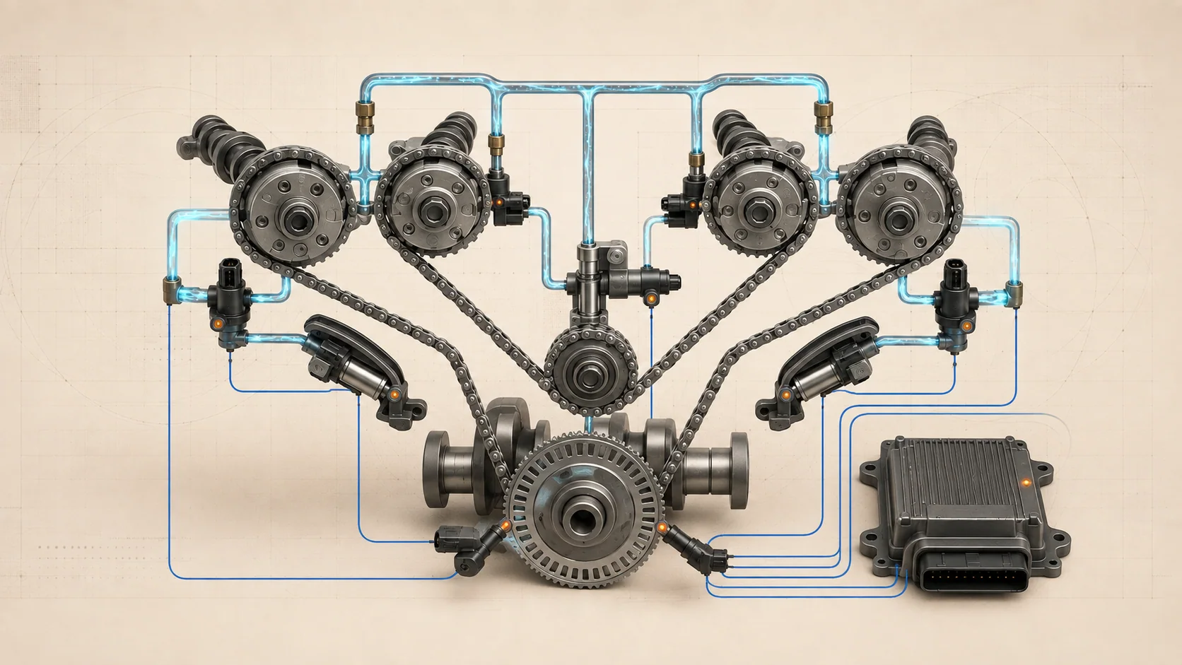
The powertrain control module (PCM) must know where the crankshaft and camshafts are, keep their signals synchronized, and adjust valve timing as operating conditions change. On the Ram 1500DT 3.6-liter Pentastar, this work connects a multi-chain mechanical timing drive, crankshaft and camshaft position sensing, four independently controlled camshaft phasers, engine-oil pressure, and a learned crankshaft correction used for misfire monitoring.
The linked STEP guides use the 2019-2025 educational vehicle grouping. Private service-information targets confirm the displayed Ram 1500 3.6L eTorque configuration at 2019, 2022, and 2025. The detailed operating descriptions and diagnostic paths reviewed for this overview are from the exact 2025 Ram 1500 Truck 4WD V6-3.6L eTorque application. Confirm the VIN, calibration, engine installation, connector details, scan-tool functions, specifications, and current service procedure before testing. Do not carry exact thresholds or repair steps from one model year to another without verification.
These functions are connected but not interchangeable:
- The timing chains, sprockets, guides, and tensioners maintain the physical crankshaft-to-camshaft relationship.
- The crankshaft position (CKP) sensor supplies the PCM with crank position and engine-speed information.
- The camshaft position (CMP) signals identify camshaft position within the engine cycle and provide feedback for variable valve timing (VVT).
- VVT solenoids and oil-control valves route pressurized engine oil into the camshaft phasers.
- The PCM compares commanded and actual cam position, checks crank/cam correlation, and stores learned crankshaft variation for accurate misfire monitoring.
A DTC identifies evidence the PCM could not validate. It does not automatically prove that the named sensor, solenoid, phaser, timing chain, or PCM has failed.
The main functional sections
- Mechanical timing drive: A primary chain drives an idler assembly, and separate secondary chains drive the camshafts in each cylinder head. Guides and hydraulic tensioners control chain movement. A separate chain drives the oil pump.
- CKP sensor and tone wheel: The CKP sensor reads a repeating magnetic target pattern. The PCM recognizes the reference feature in that pattern to establish crank angle, engine speed, and synchronization.
- CMP sensing and tone wheels: CMP sensors read magnetic tone-wheel patterns so the PCM can identify cam angle and obtain feedback for bank-specific valve-timing control.
- Four camshaft phasers: Each intake and exhaust camshaft has a phaser integrated with its sprocket. The phaser changes cam angle relative to the driven sprocket and returns toward a parked relationship when active phasing is not required.
- VVT solenoids and oil-control valves: The PCM controls each solenoid, which moves an oil-control spool. The spool routes oil to advance, hold, or retard the corresponding phaser.
- Engine-oil supply: Oil galleries feed the timing-chain tensioners, camshaft bearings, and phasers. Oil level, condition, viscosity, pressure, aeration, and restrictions can therefore affect timing control.
- PCM synchronization and learning: The PCM recognizes CKP and CMP patterns, compares their relationship, commands VVT, observes response, and stores crankshaft variation compensation for misfire monitoring.
How position sensing, correlation, and VVT work together
The CKP signal gives the PCM a detailed picture of crankshaft movement. The CMP signals identify where each camshaft is within the four-stroke cycle. Once the PCM recognizes the patterns, it can synchronize fuel injection and ignition events and judge whether the camshafts are where mechanical timing and the VVT commands say they should be.
When valve-timing adjustment is requested, the PCM pulse-width-controls the appropriate VVT solenoid. The solenoid moves the oil-control valve, which directs pressurized oil into the phaser. Oil pressure moves the phaser rotor and changes camshaft angle relative to the sprocket. CMP feedback lets the PCM compare actual movement with its target.
This architecture creates several distinct diagnostic questions. A solenoid circuit can be open even when the timing chain is correctly installed. A valid command can be followed by slow cam movement because oil supply, the spool valve, or the phaser is restricted. Stable CKP and CMP signals can be out of relationship because a chain, sprocket, phaser, tensioner, guide, or tone wheel has shifted. A missing learned crankshaft value can disable reliable misfire monitoring while the engine still has a usable CKP signal.
What the related DTCs are telling you
| DTC | Diagnostic category | What it directs you to prove |
|---|---|---|
| P0010 | Bank 1 camshaft actuator circuit open | Whether the VVT solenoid command circuit, terminals, wiring, solenoid, and PCM control are electrically intact before evaluating hydraulic or mechanical response |
| P0016 | Bank 1 exhaust camshaft-to-crankshaft misalignment | Whether two recognized position patterns are genuinely out of relationship because of oil-control, phaser, tone-wheel, chain, sprocket, guide, tensioner, or base-timing conditions |
| P0315 | Crankshaft variation value not learned | Whether related timing or misfire faults are resolved and the required crankshaft compensation can be learned and stored |
| P0335 | CKP sensor circuit or missing pattern recognition | Whether reference, ground, signal, connector, mounting, sensor, tone wheel, and PCM recognition are sound |
| P0340 | Bank 1 CMP sensor circuit or missing pattern recognition | Whether the bank-specific CMP reference, ground, signal, connector, mounting, sensor, tone wheel, and PCM recognition are sound |
P0016 is not simply another form of P0335 or P0340. The reviewed strategy requires credible, recognized CKP and CMP patterns before it judges their alignment. Resolve missing, unstable, or circuit-related position signals before relying on a correlation conclusion.
What the driver or technician may notice
Possible observations include:
- a malfunction indicator lamp with little immediate drivability change;
- extended cranking while the PCM tries to establish synchronization;
- normal operation or nonspecific drivability symptoms, depending on the underlying fault;
- start/stop operation disabled while an applicable fault is active;
- a timing, position, or P0315 code after sensor, PCM, engine, valvetrain, flexplate, chain, sprocket, or phaser work;
- companion position-sensor, VVT, correlation, oil-pressure, or misfire DTCs.
Symptoms alone do not identify the failed branch. Begin with the complete code set, failure records, scan data, and recent repair history.
Safety before testing or relearning
Many timing and position checks require a running engine, commanded camshaft movement, or controlled changes in engine speed. Work in a ventilated area, set the parking brake, secure the truck against movement, and keep hands, leads, tools, clothing, and loose objects away from belts, pulleys, fans, and hot exhaust parts. Do not stand in line with a rotating fan or in front of or behind an unsecured vehicle.
Follow the exact scan-tool prompts and abort conditions for the truck. Do not repeatedly command a learn or VVT test while a mechanical fault, unstable position signal, oil-pressure problem, low battery condition, or prerequisite DTC remains unresolved.
On eTorque-equipped trucks, follow the current electrified-powertrain and automatic-restart disablement procedure before hands-on work near rotating components. Verify that the vehicle cannot restart before placing hands, leads, or tools in the engine bay.
Before disconnecting sensors, solenoids, or PCM connectors, follow the applicable power-down and battery procedures. Engine oil and components may be hot. Mechanical timing work requires the current alignment method, holding tools, one-time-use parts, sealing instructions, torque sequence, oil-system preparation, and verification procedure.
Common failure categories
1. CKP or CMP circuit and signal fault
Reference, low-reference, and signal circuits can be open, shorted, resistive, loose, corroded, or intermittent. A sensor may be incorrectly seated, its mounting surface may be damaged or contaminated, or the target pattern may be damaged.
Use scan data, terminal-safe circuit tests, inspection, and a controlled harness check to prove the path. A code name is not a component verdict.
2. VVT solenoid circuit fault
P0010 begins as an electrical problem. Prove the command circuit, connector, terminals, wiring, solenoid electrical condition, and PCM recognition before blaming oil pressure or the phaser. A working scan-tool command does not prove that current reaches the solenoid correctly under load.
3. Oil-control or hydraulic-response fault
The phasers and several chain tensioners depend on engine oil. Low level or pressure, incorrect or degraded oil, aeration, restriction, an unsuitable filter, debris in an oil-control valve, a sticking spool, or internal phaser leakage can slow or prevent cam movement.
Compare commanded and actual cam behavior only after the electrical command is trustworthy. Check oil condition and supply using the exact current procedure before replacing a phaser.
4. Mechanical timing or tone-wheel relationship has shifted
Chain wear, incorrect installation, sprocket movement, damaged guides or tensioners, a phaser that does not return correctly, or a misaligned tone wheel can change the relationship between otherwise stable CKP and CMP signals.
Do not open the timing drive solely because P0016 is stored. First establish signal credibility and follow related-code priority; then inspect the supported mechanical branch.
5. Crankshaft variation learn is missing
P0315 reports that the PCM does not have the compensation it needs for accurate misfire monitoring. It can appear after PCM or related engine-position service. It is not proof that the CKP sensor is defective.
Resolve timing and misfire faults first. Perform the exact learn only when prerequisites are satisfied, and investigate signal or mechanical causes if the learn will not complete.
6. Several codes share one primary cause
A shared reference fault can disturb more than one sensor. A missing position signal can prevent synchronization and invalidate correlation checks. An oil-supply problem can affect multiple phasers and tensioners. A mechanical timing fault can create correlation, VVT-response, and misfire evidence without separate component failures.
Prioritize the codes according to current service information instead of diagnosing each one as an isolated failed part.
A practical diagnostic strategy
Step 1: Confirm applicability and preserve evidence
Verify the VIN, engine configuration, calibration, and current service information. Record active, pending, and stored DTCs, failure records, CKP/CMP synchronization or activity, commanded and actual cam positions, oil data, and learn status before clearing anything.
Step 2: Classify the fault
Separate the concern into a position-sensor circuit, VVT-solenoid circuit, hydraulic response, crank/cam correlation, or variation-learn state. This determines whether the next useful evidence is circuit integrity, signal stability, command response, oil supply, mechanical alignment, or a controlled learn.
Step 3: Resolve prerequisite and shared faults
Follow the exact code-priority instructions. Address shared reference, sensor-signal, power, communication, oil-pressure, or related VVT faults before relying on correlation tests or attempting a learn.
Step 4: Check oil and recent service history
Verify the specified oil level, condition, viscosity, filter application, and pressure when directed. Ask whether the concern began after oil service, sensor replacement, PCM work, flexplate work, valvetrain repair, or timing-system service.
Step 5: Prove CKP and CMP signal stability
Determine whether the PCM can recognize each position pattern consistently. Inspect connectors, harness routing, mounting, and recent disturbance. Move toward tone-wheel or mechanical inspection only when circuit and signal evidence supports it.
Step 6: Separate VVT command from VVT response
For P0010, prove the solenoid circuit first. When the command is valid, compare actual cam movement with the target using the applicable test. A correct command with incorrect movement points toward oil supply, spool movement, phaser operation, or mechanical timing rather than the command circuit.
Step 7: Evaluate correlation only after both signals are credible
For P0016, confirm stable CKP and the applicable CMP signal, then evaluate oil-control behavior, phaser return, tone-wheel alignment, chains, sprockets, guides, tensioners, and base timing in the directed order. Do not reuse exact angular limits or alignment procedures from another year or engine.
Step 8: Perform the crank variation learn when appropriate
Use the exact scan-tool routine and driving or operating conditions only after blocking faults and mechanical concerns are resolved. If the learn does not complete, stop repeating it and diagnose the listed prerequisites, signal stability, or mechanical relationship.
Step 9: Verify the complete repair
Restore every connector, retainer, oil connection, cover, and protective part. Complete required programming or learns, reproduce the original operating conditions, and confirm stable synchronization, correct cam response, plausible correlation, stored learn status, and no returning pending DTCs.
Clearing codes without rerunning the relevant monitor or required learn is not repair verification.
Match the repair to the proven failure
The supported repair may involve wiring or terminal repair, connector service, correct sensor installation, a CKP or CMP sensor, tone-wheel correction, a VVT solenoid or oil-control valve, restoring the correct oil and filter condition, correcting oil pressure, phaser service, timing-chain/guide/tensioner repair, or completing the required learn. PCM replacement or programming belongs at the end of an applicable diagnostic path, not at the beginning.
Mechanical timing work is precision work. Use current service information for alignment, holding, fasteners, sealing, torque, oil-system preparation, programming, and final verification.
Final takeaway
The Ram 1500DT 3.6 Pentastar timing system combines a two-stage chain drive, four independently controlled camshafts, oil-operated phasers, CKP and CMP pattern recognition, crank/cam correlation, and learned crankshaft variation. Diagnose those functions as separate layers.
Start with applicability and stored evidence, classify the DTC, prove the position signals, separate electrical command from hydraulic response, inspect mechanical timing only when the evidence points there, and complete the required learn and post-repair verification. The linked STEP guides provide model-specific educational context; current service information for the exact truck controls every test condition, specification, component location, relearn, and repair procedure.