What the system does
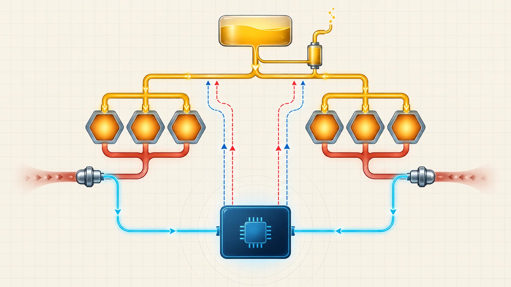
The fuel delivery and air-fuel control system must supply clean gasoline, meter it into the engine, and continually correct the mixture as airflow, load, temperature, vapor purge, and combustion conditions change. The powertrain control module (PCM) coordinates injector operation with intake information and exhaust oxygen feedback, then learns correction over time.
STEP groups the related Ram 1500DT 3.6L Pentastar Gas guides under model years 2019 through 2025. The detailed diagnostic evidence reviewed for this overview comes from the exact 2025 4WD 3.6L eTorque MHEV application. Confirm the VIN, engine and eTorque configuration, calibration, fuel-system hardware, wiring, and current service information before testing. Exact values and procedures can differ within the grouped range.
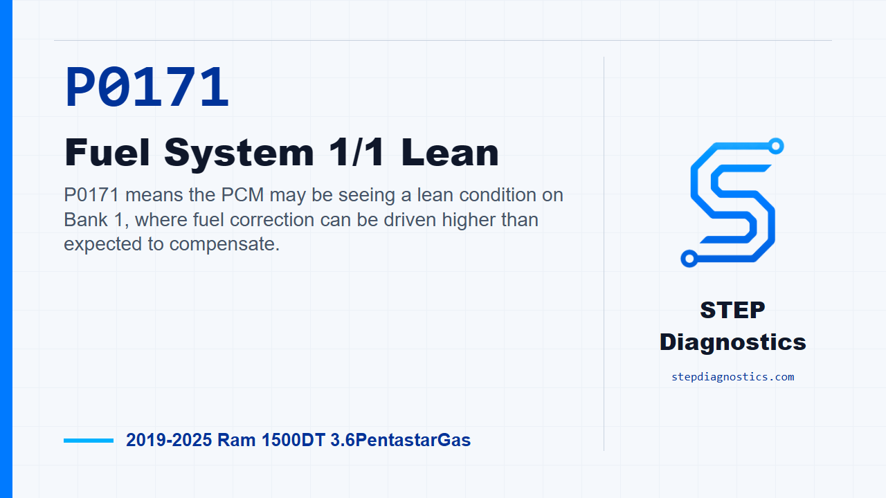
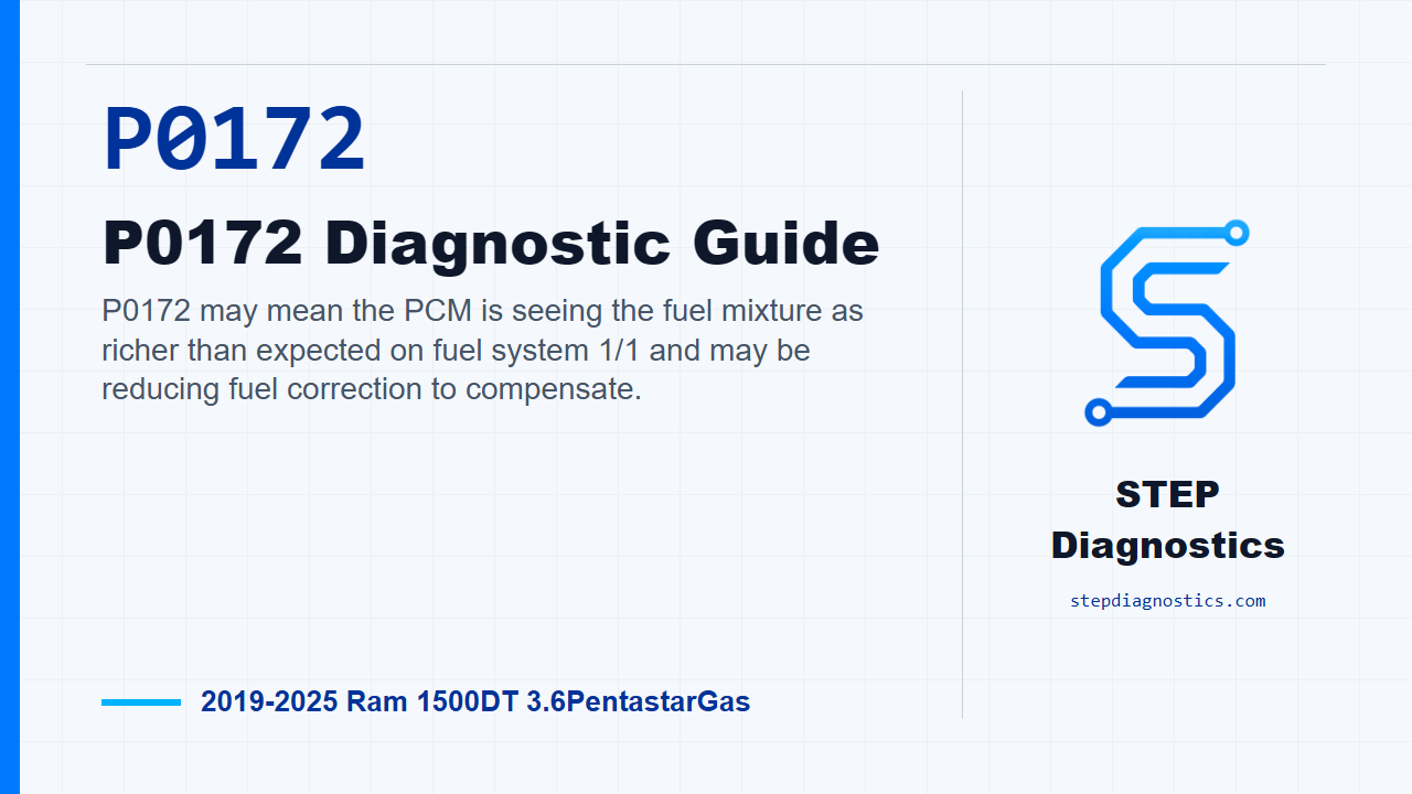
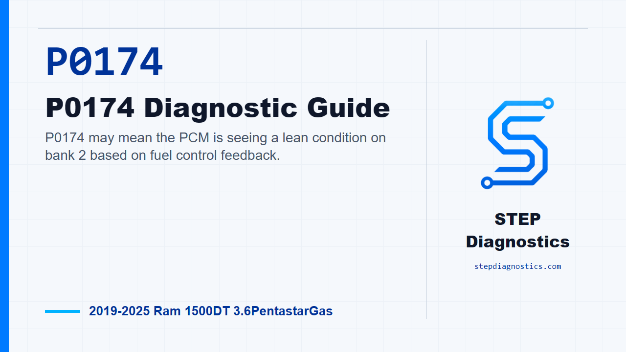
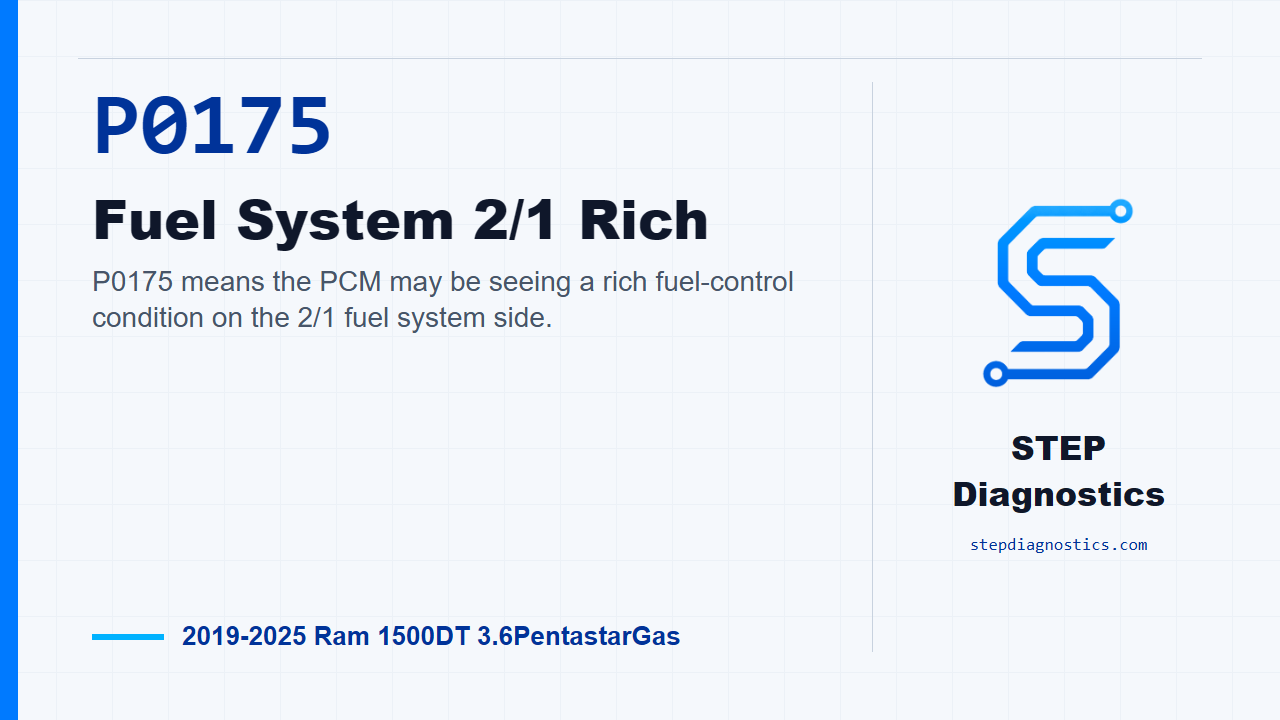
A fuel-trim DTC reports that the PCM had to correct the mixture beyond a calibrated boundary. It does not identify the failed part. P0171 and P0172 report opposite correction directions for Bank 1; P0174 and P0175 do the same for Bank 2. The technician must still prove whether air, fuel, purge, exhaust feedback, wiring, or engine condition caused the result.
Main functional sections
- Fuel supply: The delivery path, fuel quality, pressure, and available volume must remain suitable for engine demand.
- Fuel metering: Each injector must receive correct electrical control and deliver an appropriate, consistent amount of fuel to its cylinder.
- Air and load information: Manifold-pressure and related load information help the PCM establish the starting fuel command.
- Exhaust feedback: Upstream oxygen sensors show whether combustion on each bank is trending richer or leaner than the target so the PCM can correct injector command.
- Adaptive correction: Short-term fuel trim reacts to current error. Long-term fuel trim records correction that persists. Their direction and distribution are evidence, not a component test.
- Vapor influence: Purge flow introduces stored fuel vapor into the intake. Uncommanded or excessive purge can shift mixture without an injector or pump failure.
- Catalyst-related feedback: Downstream oxygen information also participates in the controller's emissions strategy. It must not be mistaken for direct proof of fuel delivery or injector condition.
How the feedback loop works
The PCM estimates how much fuel the incoming air requires and commands injector pulse width. Once the system is in closed loop, upstream oxygen feedback shows whether the result is richer or leaner than intended. Short-term trim responds quickly; long-term trim represents correction that has persisted.
Positive correction means the PCM is adding fuel relative to its base calculation. Negative correction means it is subtracting fuel. The direction is useful, but the value alone does not identify the cause. Unmetered air, restricted or excessive delivery, incorrect fuel, purge flow, biased load information, exhaust leakage or restriction, oxygen-sensor circuit trouble, injector behavior, ignition, and engine mechanical faults can all influence the feedback loop.
Bank behavior narrows the field. A large correction isolated to one bank favors a bank-specific intake leak, exhaust leak, injector issue, sensor path, wiring branch, or mechanical condition. Similar correction on both banks raises the priority of shared fuel supply, intake information, purge, fuel quality, or another common influence. The stored operating condition and the way trims change with engine state provide context, but neither authorizes a parts replacement by itself.
What the related DTCs tell you
| DTC | Diagnostic category | What it directs you to prove |
|---|---|---|
| P0171 | Bank 1 lean correction | Whether unmetered air, insufficient delivery, a restricted injector, purge influence, exhaust leakage, load-input bias, oxygen-feedback error, wiring, or engine condition caused excessive positive correction |
| P0172 | Bank 1 rich correction | Whether excessive fuel, injector leakage, purge leakage, restricted intake or exhaust, biased input, oxygen-feedback error, wiring, or engine condition caused excessive negative correction |
| P0174 | Bank 2 lean correction | Whether a Bank 2-specific problem or a shared air, fuel, purge, exhaust-feedback, electrical, or mechanical fault explains the lean result |
| P0175 | Bank 2 rich correction | Whether a Bank 2-specific or shared excess-fuel, injector, purge, restriction, input, feedback, wiring, or mechanical fault explains the rich result |
P0171 is not proof that the Bank 1 oxygen sensor failed. P0172 is not proof that a Bank 1 injector is leaking. P0174 is not an instruction to replace Bank 2 injectors. P0175 is not proof that fuel pressure is excessive. Each code identifies the bank and failed control direction; the cause remains to be tested.
What the driver or technician may notice
Possible observations include:
- a malfunction indicator lamp;
- rough running, hesitation, reduced power, fuel odor, reduced fuel economy, or no obvious complaint beyond the stored code;
- stop/start disabled while a fuel-system fault is active on an equipped truck;
- positive or negative correction concentrated on one bank or shared by both banks;
- a pattern that changes with load, temperature, engine speed, or purge influence;
- companion fuel, air-handling, oxygen-sensor, injector, ignition, or manifold-pressure codes.
Symptoms help reproduce the fault, but they do not identify the failed component. Similar drivability effects can arise from air, fuel, ignition, wiring, feedback, or mechanical causes.
Safety before testing
Gasoline and fuel vapor ignite easily, and the fuel system can retain pressure after the engine is switched off. Work in a ventilated area away from flames, sparks, smoking, hot surfaces, and unapproved electrical equipment. Wear suitable eye or face protection and gloves, contain released fuel, clean spills immediately, and follow the exact pressure-relief procedure before opening any line, rail, pump, or injector connection.
Inspect for external leakage before running the engine and stop testing if a leak is found. Let hot engine and exhaust components cool before working nearby. Support the vehicle correctly if access underneath is required.
Use terminal-safe probes and the exact wiring information. Do not force test leads into terminals, apply improvised power to injector or control circuits, or probe PCM terminals. A connector view or procedure from another engine or model year is not a safe substitute for current service information for the exact truck.
The source application includes eTorque equipment. Fuel-system diagnosis is not authorization to open, disconnect, or test eTorque components. If access or a directed test intersects that system, follow current VIN-specific service information and its required safety or disable steps.
Common failure categories
1. Unmetered air or intake leakage
A split hose, intake sealing leak, brake-booster leak, crankcase-ventilation fault, loose duct, or related sealing problem can add air the PCM did not account for. A bank-specific leak may affect one side more strongly; a shared leak can affect both banks.
2. Fuel supply or fuel-quality problem
A weak pump, restricted pickup or line, poor electrical supply, pressure-control problem, contamination, or unsuitable fuel can create a lean correction, especially under demand. Excessive delivery or poor fuel quality can shift correction rich. Prove delivery in the stored operating condition before replacing supply components.
3. Injector flow or leakage problem
A restricted injector can drive its bank lean, while a leaking injector can drive it rich. Electrical command, flow, leakage, and cylinder contribution are separate questions. Replace an injector only when the supported test branch identifies it.
4. Purge-system influence
A purge valve that does not seal, incorrect vapor flow, or damaged vapor plumbing can change mixture without a primary injector or pump failure. Because purge influence varies with operating state, compare command and observed behavior using the exact directed test.
5. Airflow, pressure, or temperature input bias
Incorrect manifold-pressure or related load information can make the PCM calculate the wrong base fuel command. Compare related data for plausibility and test the circuit before condemning a sensor.
6. Exhaust or oxygen-feedback problem
An exhaust leak can introduce oxygen and create a false lean indication. A restricted exhaust, biased oxygen sensor, damaged wiring, poor terminal fit, or slow response can distort correction in either direction. A fuel-trim code records the PCM response; it does not prove that the reporting sensor caused it.
7. Ignition or engine mechanical problem
Weak ignition, compression loss, valve-timing trouble, air restriction, or another combustion fault can change exhaust oxygen and fuel correction. Misfire data, cylinder contribution, compression, and mechanical evidence keep a combustion problem from being misdiagnosed as fuel delivery.
8. Wiring, connection, or controller problem
Corrosion, spread terminals, abrasion, heat damage, poor grounds, signal faults, and intermittent harness movement can corrupt sensor or actuator behavior. The PCM belongs at the end of a proven path after powers, grounds, circuits, inputs, outputs, loads, and connections pass their directed checks.
A practical diagnostic strategy
1. Preserve the evidence
Read and record DTCs from all modules and preserve the related freeze-frame or snapshot information before clearing codes. Confirm whether the fuel system was in the applicable closed-loop state and whether the fault is active, pending, stored, or intermittent. Record the operating condition and all companion fuel or air-handling codes before choosing the next branch.
2. Establish code priority
Review the complete code list and diagnose applicable related fuel or air-handling faults before continuing down a fuel-trim performance path. Follow the current service-information priority when several codes are present.
3. Check safety and visible evidence
Look for fuel leakage, damaged lines, loose intake plumbing, split vacuum or crankcase-ventilation hoses, disturbed purge plumbing, connector damage, heat exposure, abrasion, contamination, and exhaust leakage. Visual evidence should choose the next test, not replace it.
4. Compare banks and operating conditions
Determine whether correction is isolated to Bank 1, isolated to Bank 2, or similar on both banks. Compare the stored condition with other permitted engine states only when the exact procedure allows it. Bank and condition patterns help rank branches; they do not authorize parts replacement.
5. Separate air, fuel, purge, and feedback
Use evidence-supported tests for intake sealing, fuel delivery and quality, injector flow or leakage, purge sealing, load-input plausibility, exhaust leakage or restriction, and oxygen-sensor response. Do not use an exact value from another engine, year, or configuration. One plausible PID does not prove the entire system.
6. Verify electrical integrity
Inspect connector and terminal condition, then test powers, grounds, signals, control circuits, and harness movement with the correct terminal-safe method. Do not bypass loads or assume a good visual inspection proves circuit integrity.
7. Check ignition and engine mechanics when indicated
If air and fuel evidence does not explain the result, use misfire, cylinder-contribution, compression, leakage, valve-timing, and exhaust-flow evidence to evaluate combustion and mechanical causes. Unburned oxygen from a misfire can resemble a lean mixture at the sensor.
8. Verify the repair
Correct the proven cause, inspect for leakage, and clear codes or learned values only when the exact procedure directs it. Repeat the applicable monitor or safe operating condition, confirm that correction and oxygen feedback normalize, verify restored drivability, and re-scan all modules. A cleared lamp or a monitor that has not rerun is not proof of repair.
Repair direction by confirmed cause
- Repair intake, vacuum, brake-booster, crankcase-ventilation, or sealing leaks when they explain the bank and operating-condition pattern.
- Correct fuel contamination, restriction, pump supply, pressure control, or electrical-feed faults before replacing unrelated sensors.
- Repair or replace an injector only when electrical, flow, balance, or leakage evidence identifies the fault.
- Repair purge sealing or control only after observed behavior and the exact directed test support that branch.
- Repair exhaust leaks or restrictions and oxygen-sensor circuits before using sensor output as reliable mixture evidence.
- Repair power, ground, signal, connector, terminal, or harness faults before replacing a sensor or controller.
- Correct ignition, compression, valve-timing, air-restriction, or other mechanical faults when they explain the feedback result.
- Do not replace the PCM until its powers, grounds, circuits, loads, inputs, outputs, and applicable diagnostic path support that conclusion.
What not to do
- Do not clear codes before saving the conditions that produced the fault.
- Do not replace an oxygen sensor, injector, pump, purge valve, or PCM from the DTC name alone.
- Do not treat one bank's code as proof of a shared-system failure, or matching bank codes as proof of two separate failures.
- Do not use generic fuel-pressure, trim, connector, or command values across the full 2019-2025 range.
- Do not open a pressurized fuel system without the exact relief and fire-safety procedure.
- Do not pierce wires, spread terminals, or apply battery voltage to sensor, injector, or PCM circuits.
- Do not call a repair complete until the applicable monitor has rerun and the complete vehicle re-scan is acceptable.
Final takeaway
The Ram 1500DT 3.6L Pentastar fuel and air-fuel control system is a supply chain and a feedback loop. Fuel delivery and injectors establish the commanded mixture, intake information helps calculate it, and upstream oxygen feedback lets the PCM make short- and long-term corrections. P0171 and P0174 ask why a bank required excessive positive correction. P0172 and P0175 ask why a bank required excessive negative correction. None identifies the failed part by itself. Preserve the stored condition, compare banks, separate shared causes from bank-specific causes, and prove air, fuel, purge, feedback, electrical, and mechanical branches before choosing a repair.