What the engine timing and position system does
The engine control module (ECM) must know where the crankshaft and camshaft are, keep their signals synchronized, and control camshaft timing when operating conditions call for it. On the 5.3-liter gasoline Silverado 1500, this work connects mechanical timing, crankshaft and camshaft position sensing, oil-operated camshaft actuation, and a learned crankshaft correction used for accurate misfire detection.
Official Chevrolet fitment information supports the Silverado 1500 5.3-liter V8 configuration throughout the 2019-2025 model-year range. The detailed operating and diagnostic examples in this overview were verified against 2025 Silverado 1500 4WD V8-5.3L service information. Exact engine RPO, component design, connector details, scan-tool commands, specifications, relearn conditions, and repair procedures must be confirmed in current service information for the exact truck being repaired.
This 5.3-liter V8 uses one camshaft and one camshaft actuator. Phasing that camshaft changes intake and exhaust valve-event timing together rather than controlling separate intake and exhaust camshafts.
These functions are related, but they are not interchangeable:
- The mechanical timing drive keeps the crankshaft and camshaft physically related.
- The crankshaft position (CKP) sensor supplies the primary engine-speed and crank-position signal.
- The camshaft position (CMP) sensor tells the ECM which part of the engine cycle is occurring and provides cam-position feedback.
- The camshaft actuator and solenoid use controlled engine-oil flow to move valve timing relative to crankshaft position.
- The crankshaft position variation learn stores a correction that helps the ECM distinguish true combustion-speed changes from normal mechanical variation.
A DTC identifies the behavior the ECM could not verify. It does not, by itself, prove that a sensor, timing chain, actuator, solenoid, or control module has failed.
The main functional sections
- Crankshaft, camshaft, and timing drive: The crankshaft drives the camshaft through the mechanical timing system. Chain condition, sprocket or actuator position, tension control, installation, and the condition of the signal targets all affect the relationship the ECM observes.
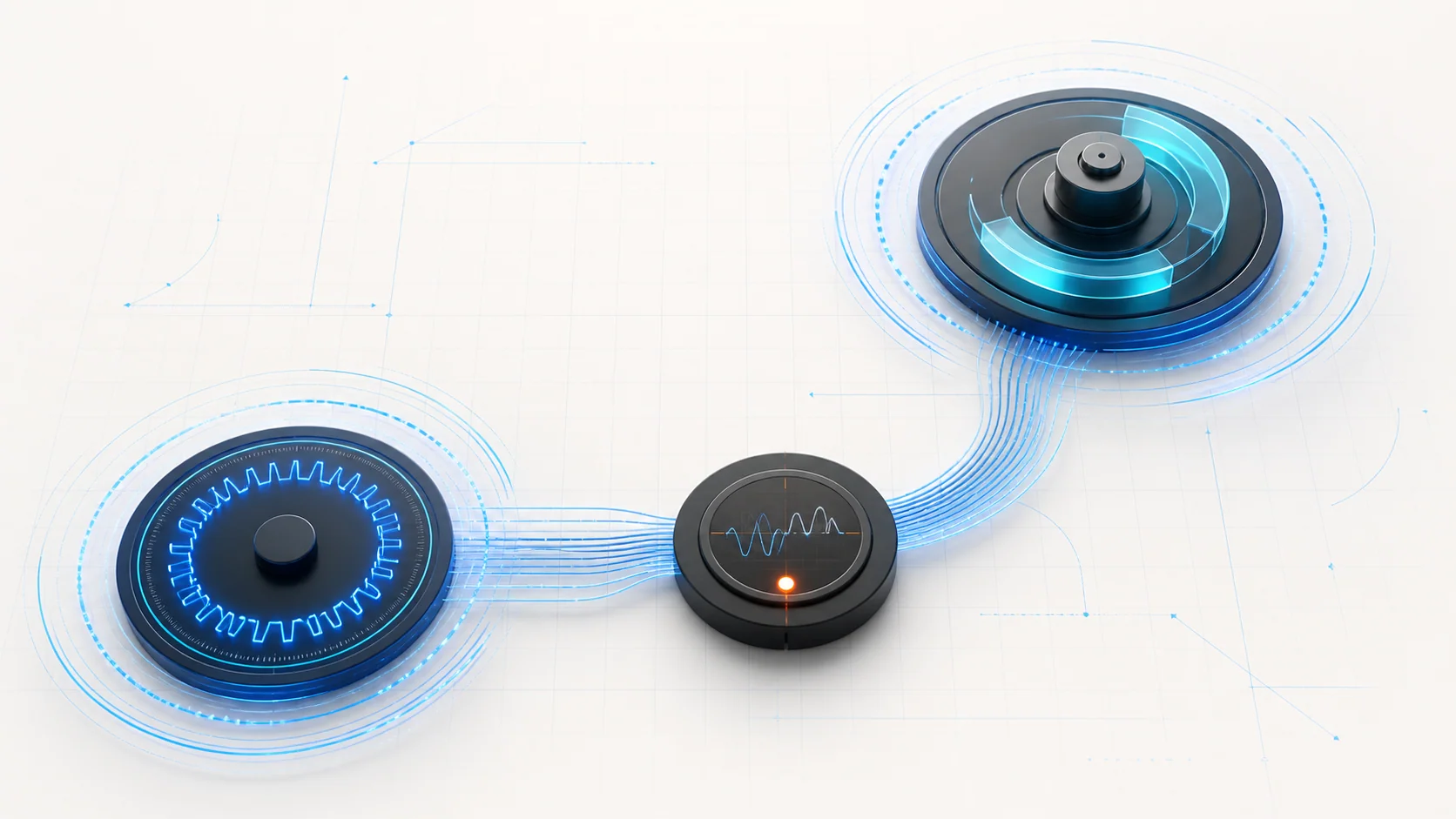
- CKP sensor and reluctor: The CKP sensor reads a repeating target pattern as the crankshaft turns. The resulting signal gives the ECM engine-speed and position information and is central to starting, ignition, injection, synchronization, and misfire evaluation.
- CMP sensor and target: The CMP signal identifies camshaft position within the engine cycle. It helps the ECM synchronize fuel and ignition events and check whether actual cam position agrees with the mechanical and commanded relationship.
- Camshaft actuator: The actuator changes camshaft angle relative to the crankshaft. It can return to and lock in a parked position when active phasing is not required.
- Camshaft actuator solenoid valve: The ECM controls the solenoid to direct engine oil through the actuator's advance or retard passages. The electrical circuit, valve movement, oil supply, and actuator response must all be separated during diagnosis.
- Engine oil supply: Oil level, condition, pressure, viscosity, and temperature influence hydraulic camshaft actuation. An oil problem can make a mechanically sound actuator respond slowly or incorrectly.
- ECM synchronization and learned variation: The ECM compares CKP and CMP signals, commands the actuator, monitors its response, and stores learned crankshaft variation so small normal differences do not imitate a misfire.
How position sensing, correlation, and variable timing work together
The CKP signal gives the ECM a detailed view of crankshaft movement. The CMP signal identifies camshaft phase within the engine cycle. With both signals present, the ECM can synchronize engine operation and compare the camshaft's position with the crankshaft's position.
When variable cam timing is requested, the ECM commands the actuator solenoid. The solenoid meters oil to the appropriate actuator passage, and hydraulic force changes the camshaft angle. The ECM then uses position feedback to determine whether the camshaft followed the command. When phasing is not required, the actuator is expected to return to its parked relationship.
Correlation is a mechanical-and-signal question. A believable CKP signal and a believable CMP signal can still be out of relationship because of timing-drive movement, an incorrectly installed part, a shifted target, or an actuator that does not return as expected. Conversely, a missing or unstable sensor signal can prevent the ECM from judging mechanical correlation at all.
Crankshaft position variation learning serves a different purpose. Small differences in the crankshaft, reluctor, and sensor relationship can change the apparent speed of individual crankshaft segments. The learn procedure stores compensation so the ECM can evaluate misfire-related speed changes more accurately. A missing learned value is not the same failure as a missing CKP signal.
What the related DTCs are telling you
| DTC | Diagnostic category | What it directs you to prove |
|---|---|---|
| P0010 | Camshaft actuator solenoid control-circuit fault | Whether the electrical command and circuit state agree, then whether the solenoid and actuator can respond once circuit integrity is established |
| P0016 | Crankshaft-to-camshaft correlation not plausible | Whether sensor installation, signal targets, actuator park behavior, or the mechanical timing relationship has shifted |
| P0315 | Crankshaft variation value not learned | Whether prerequisites are satisfied, the learn can complete, and the CKP/reluctor/mechanical relationship permits a stable correction to be stored |
| P0335 | CKP sensor circuit or no-signal fault | Whether the reference, low-reference, and signal circuits, wiring, ECM recognition, and detectable sensor activity are present. Expand into reluctor or timing diagnosis only when P0336 or other evidence supports it. |
| P0340 | CMP sensor circuit or no-signal fault | Whether the reference, low-reference, and signal circuits, wiring, ECM recognition, and detectable sensor activity are present. Expand into target or timing diagnosis only when P0341 or other evidence supports it. |
This classification prevents a common mistake: treating every timing-related code as proof that the mechanical timing drive has jumped.
What the driver or technician may notice
Possible observations depend on which function is lost:
- a malfunction indicator lamp with little immediate driveability change;
- extended cranking, a stall, or a no-start if a required position signal is absent;
- rough operation or reduced response when cam control or synchronization is affected;
- a timing or position code after sensor, engine, balancer, timing-drive, or control-module service;
- a P0315 with an engine that otherwise appears to run normally;
- related position, actuator, reference-circuit, correlation, or misfire DTCs.
The symptom does not identify the failed section. Start with the complete code set and captured operating data.
Safety before testing or relearning
Position-signal tests and relearn procedures can require a running engine and commanded changes in engine speed. Work in a ventilated area, apply the parking brake, secure the truck against movement, and keep people, tools, leads, clothing, and loose objects away from belts, pulleys, fans, and hot exhaust components. Do not stand in front of or behind an unsecured vehicle during a commanded procedure.
Follow the scan-tool prompts and abort conditions for the exact truck. Do not improvise a relearn or repeat it while a mechanical problem, unstable signal, low battery condition, or active prerequisite DTC remains unresolved.
Before disconnecting sensors, solenoids, or control-module connectors, follow the applicable power-down and battery procedures. Engine oil and components may be hot. If mechanical timing work is required, use the specified holding tools, alignment procedure, fasteners, seals, torque sequence, and verification steps from current service information.
Common failure categories
1. An electrical position-sensor fault
The CKP and CMP sensors depend on their reference, low-reference, signal, terminals, connectors, harnesses, and ECM input. An open, excessive resistance, short, poor connection, or intermittent harness movement can remove or distort the signal.
Use scan data and circuit tests to prove the path before replacing a sensor. A signal counter that drops out during a controlled harness check points in a different direction from two stable signals that remain out of correlation.
2. A camshaft actuator solenoid circuit fault
P0010 begins as a commanded-circuit-versus-observed-circuit problem. Separate the low-reference and control paths, connector integrity, solenoid electrical condition, and ECM recognition before moving into hydraulic or mechanical conclusions.
The code name mentions the actuator system, but an electrical circuit fault and a slow hydraulic response are not the same diagnosis.
3. Oil flow or hydraulic cam-control response is incorrect
The actuator depends on controlled engine-oil flow. Low level or pressure, unsuitable or degraded oil, restricted flow, a sticking solenoid valve, or an actuator problem can prevent actual cam position from following the command or returning to park.
Verify oil condition and supply using the exact procedure before condemning a mechanical actuator. Correct electrical faults first so the functional command is trustworthy.
4. Mechanical timing or target relationship has changed
P0016 asks whether the CKP and CMP relationship is plausible. Timing-drive wear or incorrect installation, actuator fitment or park problems, a misaligned or damaged reluctor or target, sensor fitment, and excessive movement can change the observed relationship.
Do not use one correlation DTC as permission to disassemble the engine. Confirm that the sensor signals and related circuits are credible, then perform the directed mechanical inspection.
5. The crankshaft variation learn is missing or cannot complete
P0315 reports learn status, not automatically a failed CKP sensor. The learned value may be missing after certain repairs or module events. If the learn fails, battery condition, signal stability, sensor-to-reluctor relationship, target alignment, and base mechanical condition become relevant.
Complete prerequisite diagnosis before repeating the learn. A failed procedure is evidence to investigate, not a reason to keep commanding the routine indefinitely.
6. Multiple codes reflect one primary fault
A missing CKP or CMP signal can prevent synchronization and make correlation or actuator tests invalid. A shared reference or connection problem can affect more than one input. A mechanical timing fault can produce correlation and performance evidence even when individual sensor circuits test normally.
Prioritize the code set according to the exact service strategy. Do not diagnose five codes as five unrelated failed parts.
A practical diagnostic strategy
Step 1: Confirm applicability and preserve evidence
Verify the model year, engine RPO, drivetrain, calibration, and applicable service procedure. Record confirmed and pending DTCs, freeze-frame or failure-record data, CKP and CMP activity, commanded and actual cam position, and learn status before clearing anything.
Step 2: Classify the codes
Separate the concern into actuator circuit, position-sensor circuit, correlation, hydraulic response, or variation-learn status. This determines whether the next useful evidence is electrical integrity, signal stability, command response, mechanical relationship, or a controlled relearn.
Step 3: Resolve prerequisite and shared faults first
Follow the exact code-priority instructions. Correct shared reference, signal, power, communication, or prerequisite DTCs before relying on correlation or actuator function tests.
Step 4: Check engine oil and recent service history
Verify the specified oil level, condition, and pressure when the applicable path calls for it. Ask whether the concern began after sensor, balancer, engine, timing, actuator, wiring, or control-module work. Recent disturbance can make installation, connector, target alignment, and required relearn status especially important.
Step 5: Prove CKP and CMP signal stability
Use the specified scan data, circuit tests, and controlled harness checks. Determine whether each signal is present and stable before judging their relationship. Inspect sensor installation and target condition only as directed by the evidence.
Step 6: Separate actuator command from actuator response
For P0010 or a cam-response concern, first prove the electrical circuit and solenoid. Then compare commanded and actual cam behavior using the applicable test. If the command is valid but response is not, evaluate oil supply, valve movement, actuator operation, and mechanical timing in the service-information order.
Step 7: Evaluate correlation mechanically only after signals are credible
For P0016, confirm that CKP and CMP circuits and installation are sound. Then inspect the actuator's parked relationship, signal targets, timing drive, and related mechanical fitment. Avoid using exact angular limits or alignment methods from another engine or model year.
Step 8: Perform the variation learn only when prerequisites are satisfied
Use the exact scan-tool routine after the repairs or conditions that require it. Confirm battery and vehicle state, resolve blocking DTCs, follow all safety prompts, and stop if the routine fails so the listed signal or mechanical causes can be checked.
Step 9: Verify the complete repair
Restore every connector, harness retainer, oil connection, cover, and protective part. Perform required programming or learns, reproduce the original operating conditions, and confirm stable signals, correct cam command response, plausible correlation, successful learn status, and no returning pending DTCs.
Clearing codes without rerunning the relevant monitor or required learn is not repair verification.
Match the repair to the proven failure
The supported repair may involve wiring or terminal repair, connector service, a CKP or CMP sensor, correction of sensor or target installation, a camshaft actuator solenoid, restoring correct oil level or pressure, an actuator or timing-drive repair, target or reluctor correction, or completing the required variation learn. Control-module work belongs at the end of an applicable diagnostic path, not at the beginning.
Mechanical timing repairs are precision work. Use current service information for alignment, holding, fasteners, sealing, torque, oil-system preparation, programming, and final verification.
Final takeaway
On a 2019-2025 Chevrolet Silverado 1500 confirmed to use the 5.3-liter gasoline V8 configuration, engine timing diagnosis is a comparison among mechanical timing, CKP and CMP signal integrity, commanded camshaft actuation, oil-supported response, and learned crankshaft correction.
Start with applicability and stored evidence, classify the DTC, prove the position signals, separate electrical command from hydraulic response, and inspect mechanical timing only when the evidence points there. The linked STEP DTC guides provide model-specific educational context; current service information for the exact truck controls every test condition, specification, component location, relearn, and repair procedure.