Quick answer
The powertrain control module (PCM) uses crankshaft-position (CKP) and camshaft-position (CMP) signals to synchronize fuel and ignition, monitor the mechanical crank-to-cam relationship, and verify oil-controlled variable valve timing (VVT). P0010 and P0013 identify electrical faults in two Bank 1 VVT actuator-control circuits. P0335 and P0340 identify missing or unreliable CKP/CMP signal paths. P0016 means recognized crank and cam patterns are no longer aligned with the learned relationship. None of these codes, by itself, proves that a sensor, solenoid, phaser, or timing chain has failed.
Applicability and service-information boundary
This overview follows STEP's 2019-2024 Ram 1500 Classic 3.6L Pentastar Gas educational grouping. Authorized vehicle records confirm Ram 1500 Classic Truck 4WD applications with the 3.6-liter V6 at the 2019 and 2024 endpoints. Detailed system operation and diagnostic evidence for this overview was verified on the exact 2024 application.
Calibration, wiring, connector details, scan-tool functions, sensor and target design, oil-pressure requirements, component access, and repair procedures can change by year and equipment. Use current service information for the exact truck whenever a test requires a value, connector, command, special tool, relearn, alignment, or removal procedure.
What the timing and position system does
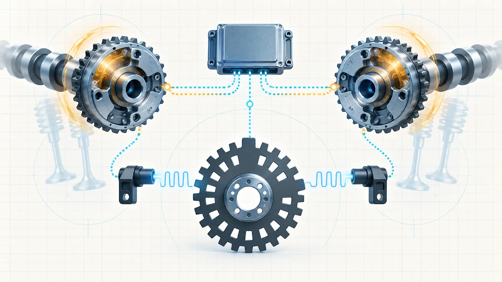
Mechanical timing establishes the physical relationship among the crankshaft, camshafts, pistons, and valves. CKP and CMP sensing tells the PCM where those rotating parts are. VVT adds a controlled change to camshaft position so the engine can meet operating and emissions requirements under different conditions.
The system has several connected layers:
- Timing chains, sprockets, guides, tensioners, phasers, and related hardware establish and maintain the mechanical relationship.
- The CKP sensor gives the PCM crankshaft position and speed information.
- CMP signals identify camshaft position within the engine cycle and provide VVT feedback.
- VVT solenoids move oil-control valves that direct engine oil to hydraulic phasers.
- The PCM models desired camshaft position, commands the solenoids, monitors actual movement, and compares the crank-to-cam relationship with learned information.
A DTC reports which monitor failed. It does not identify the failed part without further testing.
How CKP and CMP information creates synchronization
The CKP signal provides a repeating position pattern tied to crankshaft movement. CMP signals identify camshaft position within the four-stroke cycle. Once the PCM recognizes and validates these patterns, it can sequence fuel injection and ignition and track the relationship between the crankshaft and each camshaft.
The PCM does not judge correlation from one static voltage. It recognizes digital position patterns, and P0016 is evaluated only after the applicable CKP and CMP patterns are recognized. This is why a correlation code is different from a missing-signal code: both signals may be present while their relationship is wrong.
Learned relationship information is part of the evidence chain. Service involving specified position sensors, tone wheels, flywheel, valvetrain, timing components, or related hardware can require the current Cam/Crank Relearn procedure. A relearn cannot repair a noisy signal, damaged target, sticking oil-control valve, low oil pressure, or incorrect mechanical alignment.
How oil-controlled VVT changes camshaft position
The PCM calculates a target camshaft position from engine operating conditions. It controls the appropriate VVT solenoid, which moves a spring-loaded spool in the oil-control valve. Pressurized oil is routed into the phaser on the camshaft sprocket, changing camshaft angle relative to the crankshaft. CMP feedback shows the PCM how the camshaft actually moved.
This creates a command-and-response chain: electrical command, solenoid movement, oil routing and pressure, phaser movement, CMP feedback, and crank/cam comparison. A failure anywhere in that chain can keep actual cam position from matching the model.
P0010 and P0013 belong mainly to the electrical-command layer. P0335 and P0340 belong mainly to the position-signal layer. P0016 belongs to the resulting relationship layer. These codes can occur together when one primary fault affects more than one monitor, but each requires its own diagnostic classification.
What the related DTCs are telling you
| DTC | Diagnostic category | What it directs you to prove |
|---|---|---|
| P0010 | Bank 1 camshaft 1 actuator-control circuit | Whether the control and ground paths, connector/terminals, harness, solenoid, and controller-side command are electrically sound before hydraulic or mechanical conclusions |
| P0013 | Bank 1 camshaft 2 actuator-control circuit | Whether the exhaust-cam VVT command path and solenoid branch are electrically intact before oil-control or phaser testing |
| P0016 | Bank 1 crankshaft/camshaft timing misalignment | Whether recognized CKP and CMP patterns remain correctly related, then whether oil condition and pressure, VVT response, tone-wheel alignment, phaser condition, or mechanical timing explains the deviation |
| P0335 | CKP sensor circuit or missing pattern recognition | Whether supply, ground, signal, connector, harness, mounting, sensor, target wheel, and PCM recognition are sound |
| P0340 | Bank 1 CMP sensor circuit or missing pattern recognition | Whether the CMP supply, ground, signal, connector, mounting, sensor, tone wheel, and PCM recognition are sound before VVT or timing conclusions |
P0016 is not another name for P0335 or P0340. The correlation monitor requires usable position patterns. Resolve missing, unstable, or circuit-related position signals before relying on a crank/cam relationship verdict.
What the driver or technician may notice
Possible observations include:
- a malfunction indicator lamp with little immediate drivability change;
- extended cranking while the PCM tries to establish synchronization;
- rough idle, hesitation, reduced response, or related misfire evidence when cam timing is affected;
- stop/start operation that becomes unavailable while a relevant fault is active;
- a fault that begins after oil service, sensor work, valvetrain work, timing-system repair, or programming;
- an intermittent code that changes with oil temperature, engine speed, vibration, harness position, or connector movement;
- companion VVT, oil-pressure, position-signal, correlation, or misfire DTCs.
Symptoms do not identify the failed branch. Preserve the complete scan and operating record before clearing codes.
Common failure categories
VVT circuit, connector, or solenoid fault
An open, short, excessive resistance, weak ground, poor terminal fit, corrosion, water intrusion, heat damage, or harness rub can keep a VVT solenoid circuit from matching the PCM command. The solenoid can fail electrically or mechanically, but P0010 or P0013 is not proof that the solenoid itself is the cause.
Inspect routing, locks, seals, terminal tension, and recent service areas. Use the current terminal-safe procedure and prove the circuit under the specified load before considering the PCM.
CKP or CMP signal-path fault
The sensor supply, ground, and signal paths can be open, shorted, resistive, loose, corroded, or intermittent. A sensor may be incorrectly seated, its mounting surface may be damaged or contaminated, or a tone wheel may be damaged or misaligned. A signal can be present yet still be unreliable.
Use scan data and the specified circuit or waveform test to prove recognition and stability. Replacing a sensor cannot correct damaged target hardware, a mounting problem, or a harness fault.
Oil condition, supply, or pressure fault
The phasers, oil-control valves, and timing-chain tensioning system depend on clean oil of the correct specification reaching them at sufficient, stable pressure. Low level, unsuitable viscosity, contamination, aeration, an incorrect filter, restricted flow, sludge, pump or pickup problems, and other oiling faults can make commanded VVT movement slow, incomplete, or unstable.
Verify oil level, condition, service history, filter application, and directed pressure evidence before condemning a phaser or opening the timing drive.
Oil-control valve or phaser fault
An oil-control spool can stick or respond inconsistently even when its electrical circuit passes. A phaser can bind, respond incorrectly, fail to return to its parked relationship, or provide feedback that does not follow the commanded target.
Compare commanded and actual behavior only after electrical integrity and oil supply are credible. A scan-tool command is useful evidence only when all prerequisites are satisfied.
Tone-wheel or mechanical timing fault
A loose, damaged, or misaligned tone wheel can change the pattern relationship. Incorrect chain or sprocket alignment, chain wear, a damaged guide or tensioner, a phaser problem, or an assembly error can shift the physical crank-to-cam relationship.
This branch becomes credible after signal quality is proved, prerequisite electrical faults are resolved, and oil/VVT evidence is known. Do not begin with engine disassembly only because P0016 is stored.
Recent-service or relearn problem
A loose connector, incorrect oil or filter, disturbed target, sensor installation problem, misassembled timing hardware, or omitted relearn can create a post-repair fault. Review the repair timeline before treating the code as unrelated.
Complete the specified relearn only after the physical and electrical system is sound. Repeatedly commanding a relearn is not a substitute for diagnosis.
A practical system-first diagnostic strategy
Step 1: Confirm applicability and preserve evidence
Verify the VIN, model year, 3.6-liter configuration, calibration, and current service information. Save the complete module scan, active/pending/stored DTCs, failure records, CKP/CMP synchronization or activity, commanded and actual cam data, oil information, and recent repair history before clearing anything.
Step 2: Classify the primary fault
P0010/P0013 direct you first to VVT command circuits. P0335/P0340 direct you to position-signal paths. P0016 requires recognized signals and directs you toward the resulting crank/cam relationship, oil/VVT response, target condition, and mechanical timing. Decide which layer failed before choosing tools or parts.
Step 3: Resolve prerequisite and shared faults first
Follow current code-priority instructions. Diagnose active reference, power, ground, position-signal, VVT electrical, oil-pressure, or related misfire faults before relying on a correlation conclusion. One shared condition can produce several codes.
Step 4: Inspect oil and recent service history
Verify the specified oil level, condition, viscosity, filter application, and pressure when directed. Ask whether the concern began after oil service, sensor or harness work, valvetrain repair, timing-system work, flywheel work, or control-module programming.
Step 5: Prove electrical paths and position signals
Inspect harnesses and connectors, then isolate supply, ground, control, and signal integrity using the exact procedure. Determine whether the PCM recognizes stable CKP and CMP patterns. Look for dropout, noise, poor terminal contact, or a relationship that changes with temperature, vibration, or engine speed.
Step 6: Separate VVT command from VVT response
When the electrical command and position inputs are credible, compare commanded cam movement with actual feedback under valid conditions. A valid command with incorrect movement points toward oil supply, oil-control valve, phaser, or mechanical timing rather than the command circuit.
Step 7: Inspect mechanical timing only when supported
Evaluate tone-wheel alignment, chain and sprocket alignment, guide and tensioner condition, phaser return, and related mechanical fitment only after earlier evidence supports this branch. Use the exact alignment tools, holding procedures, fasteners, sealing instructions, lubrication steps, and torque specifications for the truck.
Step 8: Perform required learning and verification
After specified position-sensor, tone-wheel, flywheel, valvetrain, timing-drive, or related work, complete the current Cam/Crank Relearn with every prerequisite satisfied. Reproduce the original operating conditions, confirm stable position recognition and cam response, rerun the relevant monitor, and verify that no pending or confirmed DTC returns.
Safety before testing or relearning
Position and VVT tests may require cranking, a running engine, or controlled changes in engine speed. Work in a ventilated area, set the parking brake, secure the truck against movement, and keep hands, clothing, tools, leads, and loose objects away from belts, pulleys, fans, and hot exhaust parts. Do not stand in front of or behind an unsecured truck during a commanded procedure.
Follow the current battery and power-down procedure before disconnecting sensors, solenoids, or PCM connectors. Engine oil and timing components can be hot. Stop a functional test or relearn if the engine behaves abnormally or a prerequisite is not satisfied.
Match the repair to the proven failure
The supported repair may involve terminal or wiring repair, connector service, correct sensor or solenoid installation, replacing a proved CKP/CMP sensor or VVT solenoid, correcting a tone-wheel concern, restoring the correct oil and filter condition, repairing an oil-pressure or oil-flow problem, servicing an oil-control valve or phaser, correcting chain/guide/tensioner hardware or mechanical alignment, or completing the required relearn. PCM work belongs at the end of the applicable diagnostic path.
Mechanical timing repairs are precision work. Current service information for the exact truck controls alignment, holding, one-time-use parts, torque, sealing, lubrication, programming, learning, and final verification.
Final takeaway
On the 2019-2024 Ram 1500 Classic 3.6L Pentastar Gas, timing diagnosis is a comparison among VVT electrical command, engine-oil support, phaser response, CKP/CMP pattern recognition, learned crank/cam relationship, and mechanical alignment.
Preserve the evidence, classify the failed layer, resolve prerequisite faults, prove position-signal quality, separate VVT command from response, and inspect mechanical timing only when the evidence points there. Complete required learning and rerun the monitor before calling the repair finished. The linked STEP guides provide model-specific educational paths; current service information for the exact truck controls specifications, commands, connectors, component locations, disassembly, and verification.